


Standard I/O Expansion Shield V5 Xbee Sensor Shield RS485 V5 Funduino Board Module
Categories :
Wireless ModulesSKU :
180324100% original guarantee
Return within 30days
Worldwide Fast delivery
You may also like
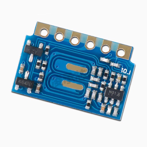
H3V3E/H3V4F 315/433MHz Wireless Receiver Module
$ 0.94 $ 0.94
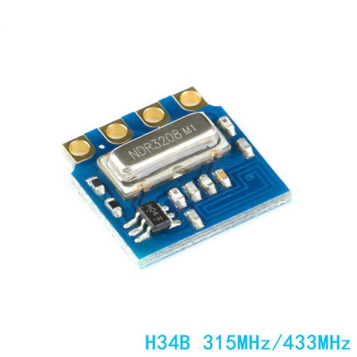
H34B Wireless Transmitter Module 315MHz 433MHz
$ 0.68 $ 0.68
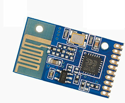
L24YK Transciver and Receiver Module
$ 1.14 $ 1.14
Description:
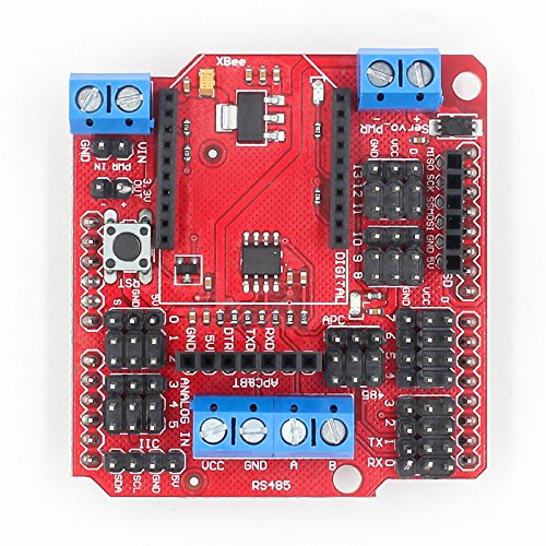
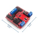
Our IO expansion board is evolving, this latest V5 IO expansion shield is now supporting Xbee. It combines our popular Xbee shield
with IO expansion shield(V4). It even supports SD card which provides the ultimate
functional expansion for Arduino so far. As its predecessor, it supports RS485, APC220,
Bluetooth communication, servo control.
Specification:
Support RS485
Support Xbee (Xbee pro)
Support Bluetooth
Support APC220
Support SD card read/write
1. extension of 14 digital IO ports (12 servo interface) and power;
2.6 analog IO ports and power;
3.1 digital external power port terminal;
4. Digital-port external power supply and an onboard power supply automatic switching;
5.1 External power input terminal and an input pin;
6.RS485 interface;
7. reset button;
8.xbee/Bluetooh Bee Bluetooth wireless data transmission interface;
9.APC220/Bluetooh V3 Bluetooth wireless data transmission interface;
10.IIC/I2C/TWI interface;
11.3.3V output port;
12.SD card module interface;
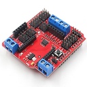
RS485:
It uses an SP485CN chip to handle comms.
The screw terminals (assuming that the three jumpers are set to '485') marked 'A' and 'B' go directly to the IC 'A' and 'B' pins (6 & 7 respectively).
The screw terminal marked VCC goes to the IC VCC pin (8), and also to the board's +5V line
The screw terminal marked GND goes to the IC GND pin (5), and also to the board's GND line
The chip's DI (Data Input?) pin (4) is connected to for Arduino's Digital Pin 1 (TX).
The chip's RO (Data Output?) pin (1) is connected to for Arduino's Digital Pin 0 (RX), with a resistor pull-up to the +5V rail.
The chip's DE (output enable) pin (3) is connected (via a resistor) to for Arduino's Digital Pin 2 - this is active high.
This DE pin is also connected to the chip's RE bar (receiver enable) pin (2) and therefore controlled by for Arduino's Digital pin 2 too - this is active low.
Digital Pin 2 = Rx/Tx 'Enable'; High to Transmit, Low to Receive
So, to transmit data from for Arduino Digital Pin 1 you need to take Digital pin 2 high, and to receive data to for Arduino Digital Pin 0 you need to take Digital pin 2 low.
It combines our popular Xbee shield