


12V ESP8266 ESP-01 4 Channel WiFi Relay Module for IOT Smart Home Phone APP Controller
Categories :
Relay ModulesSKU :
181096100% original guarantee
Return within 30days
Worldwide Fast delivery
You may also like
Overview:
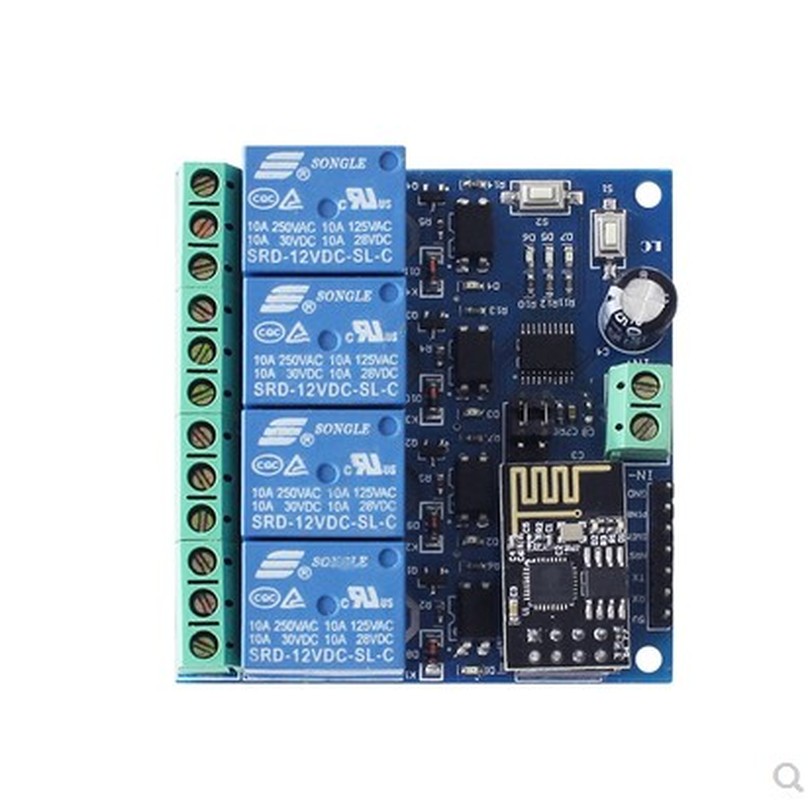
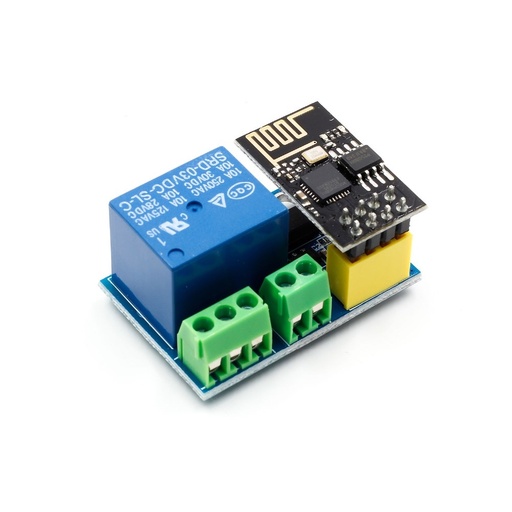
The 12V ESP8266 four-way WIFI relay module uses the ESP-01 as a WIFI module, with a mature and stable 8-bit MCU chip. It can realize the wireless control of the 4-way relay using the mobile phone APP within the LAN in a simple configuration process.
Functional characteristics:
Onboard high performance microprocessor and ESP-01 WIFI module;
The module has 2 working modes: Mode 1: The mobile phone is directly mounted on the WIFI module; Mode 2: The mobile phone and WIFI module are loaded on the router at the same time;
Additional features: It can also be used as a USB relay when the ESP-01 is unplugged.
Transmission distance:
(1) In the open environment, the maximum stable transmission distance when the mobile phone is mounted on the WIFI module is 100m;
(2) When the WIFI module and the mobile phone are mounted on the router at the same time, the transmission distance is strong according to the signal of the router.Use Smartconfig technology to complete the configuration of the ESP-01 WIFI module account and password on the mobile phone APP. The configured account and password have the power-off memory function.
On-board 12V, 10A/250V AC 10A/30V DC relay, can continuously suck 100,000 times, with diode escaping protection, short response time;
Onboard mode selection and real-time working status indicator;
With 4 optocoupler isolation, strong anti-interference ability;
Reserved UART debug interface and MCU program download interface.
Specification:
Board size: 60*63mm
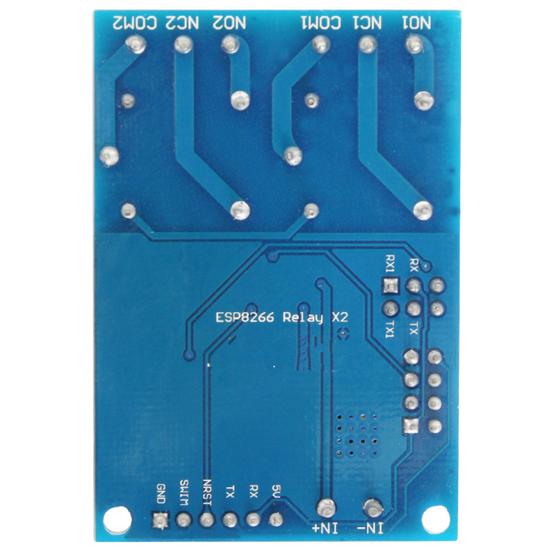
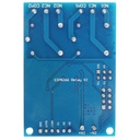
Board function description:
1, onboard resources:
IN+, IN-: 12V power input;
5V, GND, TX, RX:UART serial port pin;
SWIM, PIN8, NRST: Reserved MCU program download port.
Button S1: Mode switch, default is mode 1
Press key S2: restore factory settings
LED D1/D2/D3/D4 (red light): Relay operation indicator lighted when turned on
LED D7 (red): Mode 1 indicator
LED D5 (blue light): Mode 2 indicator
LED D6 (green light): Operating status indicator, described as follows:
(1) When it goes out, it means that it is self-configuring or losing connection with the router;
(2) When 0.5S is flashing, it means waiting for the mobile phone APP to configure the WIFI account and password for the ESP-01 module;
(3) When the 2S flashes slowly, it means that the configuration is completed, waiting for a TCP connection with the handset;
(4) When it is always on, it means that it establishes a TCP connection with the handset.
Reserved 2 jumper caps: Please plug in the bottom end when using normally (ie RX connects RX1, TX connects TX1). If you want to use USB to TTL serial port module to debug ESP-01 module, please plug it all the way to the top ( Otherwise there may be interference).
COM1: public end;
NC1: Normally closed, the relay is short-circuited with COM1 before the relay is closed, and it is vacant after being sucked up;
NO1: Normally open, the relay is vacant before being sucked in, and shorted to COM1 after sucking.
COM2: public end;
NC2: Normally closed, the relay is shorted to COM2 before the relay is closed, and it is vacant after being sucked up;
NO2: Normally open, the relay is suspended before closing, and shorted to COM2 after pull-in.
COM3: public
NC3: Normally closed, short-circuited with COM3 before the relay is closed, and it is vacant after suction;
NO3: Normally open, the relay is vacant before being sucked up, and shorted to COM3 after sucking.
COM4: public
NC4: Normally closed, shorted to COM4 before the relay is closed, and it is left open after suction.
NO4: Normally open, the relay is left unconnected before it is sucked in, and it is short-circuited with COM4 after pull-in.
Relay control instructions (hex hexadecimal):
Open the first relay: A0 01 01 A2
Turn off the first relay: A0 01 00 A1
Open the second relay: A0 02 01 A3
Close the second relay: A0 02 00 A2
Open the third relay: A0 03 01 A4
Turn off the third relay: A0 03 00 A3
Open the fourth relay: A0 04 01 A5
Turn off the fourth relay: A0 04 00 A4