


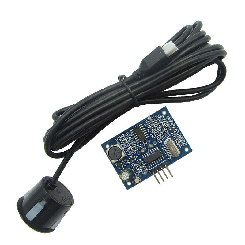
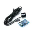


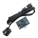

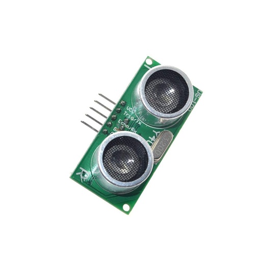
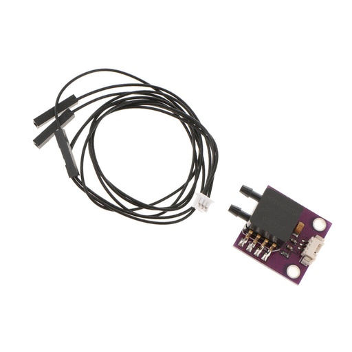
JSN-SR04T Water Proof Integrated Distance Measuring Transducer Sensor for Arduino
Categories :
Ultrasonic Sensor ModulesSKU :
180666100% original guarantee
Return within 30days
Worldwide Fast delivery
You may also like
MPXV7002DP APM 2.5 Air Speed Sensor Breakout Board Transducer
$ 10.85 $ 10.85
Electrical properties
Electrical parameters: JSN-SR04T
Operating voltage: DC 3 ~5.5V
Quiescent current: < 8mA
Acoustic emission frequency: 40khz
Farthest range: 600cm
Recent range: 20cm
Distance measurement accuracy: ± 1cm
Resolution: 1mm
Measuring angle: 75 degrees
Input trigger signal: TTL pulse above 10uS
Serial send command: 0X55
Output echo signal: Output pulse width level signal, or TTL
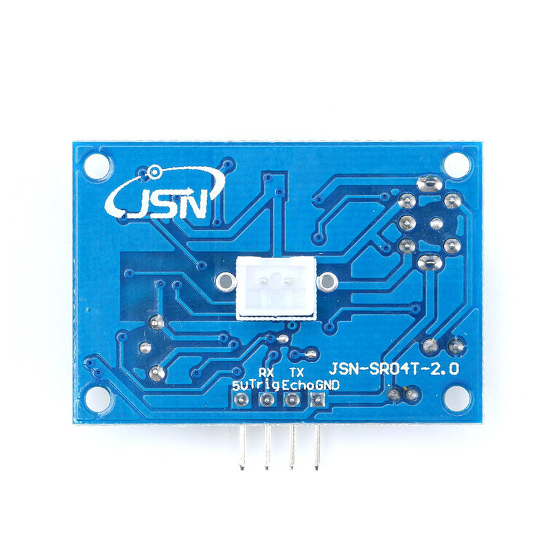
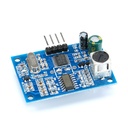
3-5.5V (power positive)
Trig (RX) RX
Echo (output) TX
GND (power supply negative
Product Size: L42 * W29 * H12 mm
Working temperature: -20 ℃ - +70 ℃
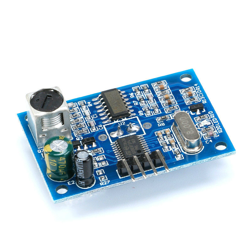
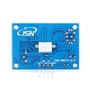
Product color: PCB board is blue
Product Features
1.Small size, easy to use
2. low power consumption
3. High accuracy
4, detection of blind spots, farther away
5, the output method of diversification, pulse width output, serial output
Note:
This module should not be charged connection, to live connection, then let the module first GND connected, otherwise it will affect the normal work of the module.
Ranging, the measured object area of not less than 0.5 square meters and the plane as required to smooth, otherwise affect the measurement results.
The default working mode is Mode 1.
Mode 1: R27 = open that is not welding. The pattern is described below
Basic working principle:
Using IO port TRIG trigger range, to a minimum of 10us high letter.
Module automatically send 8 40khz square wave, automatically detect whether the signal back;
There is a signal to return, through the IO port ECHO output a high level, the high level of continuous time is the ultrasound
From the time of launch to return. Test distance = (high time * sound velocity (340M / s)) / 2;
When the module is triggered, if no echo is received (the reason is more than the measured range or the probe is not positive On the measured object),
ECHO port will automatically become low after 60MS, marking the end of the measurement, regardless Power or not.
LED indicator, LED non-power indicator, it will receive the trigger signal after the module, this When the module is in working condition.
Only need to provide a pulse above 10uS trigger signal, the module will be issued within 8 40kHz cycle levels and detect echo. The echo signal is output once an echo signal is detected. Reverberations
The pulse width of the pulse is proportional to the measured distance. Thereby by transmitting a signal to the received echo signal time interval
Can calculate the distance. Formula: uS / 58 = cm or uS / 148 = inches; or: distance = high time *Sound speed (340M / S) / 2;
The recommended measurement period is 60ms or more to prevent the impact of the transmitted signal on the echo signal.
Mode 2: R27 = 47K is the welding 47K resistance. The pattern is described below
Serial output format for the TTL level, that: 100MS module for the cycle of automatic transmission
The value of the distance, in mm. Serial baud rate: 9600, n, 8,1.
Module power recognition, directly into the work mode, the module to conduct a distance every 100ms range,
And outputs one frame from the pin TX with four 8-bit data. The frame format is: 0XFF + H_DATA + L_DATA + SUM
1.0XFF: for a frame to start the data, used to judge;
2.H_DATA: the upper 8 bits of the distance data;
3.L_DATA: the lower 8 bits of the distance data;
4.SUM: data and, for the effect of its 0XFF + H_DATA + L_DATA = SUM (only low 8)
Note: H_DATA and L_DATA synthesize 16-bit data, that is, the distance in millimeters.
Description: The module outputs the nearest distance value in the dead zone. If the module does not measure data or is out of range Measured output 0.
LED indicator, LED non-power indicator, the module connected to work after the light, then the module is in Working state.
Mode 3: R27 = 120K is the welding 120K resistance. In the serial port mode
Module power recognition, the module into the standby state, the serial output format for the TTL level, the serial port baud rate:
9600, n, 8, 1. When the RX port receives the 0X55 instruction, the module starts a ranging and outputs from the pin TXOut of a frame with 4 8-bit data.
The frame format is: 0XFF + H_DATA + L_DATA + SUM
1.0XFF: for a frame to start the data, used to judge;
2.H_DATA: the upper 8 bits of the distance data;
3.L_DATA: the lower 8 bits of the distance data;
4.SUM: data and, for the effect of its 0XFF + H_DATA + L_DATA = SUM (only low 8)
Note: H_DATA and L_DATA synthesize 16-bit data, that is, the distance in millimeters
Description: The module outputs the nearest distance value in the dead zone. If the module does not measure data or is out of range Measured output 0.
LED indicator, LED non-power indicator, it will receive the 0X55 trigger signal in the module, this When the module is in working condition.