
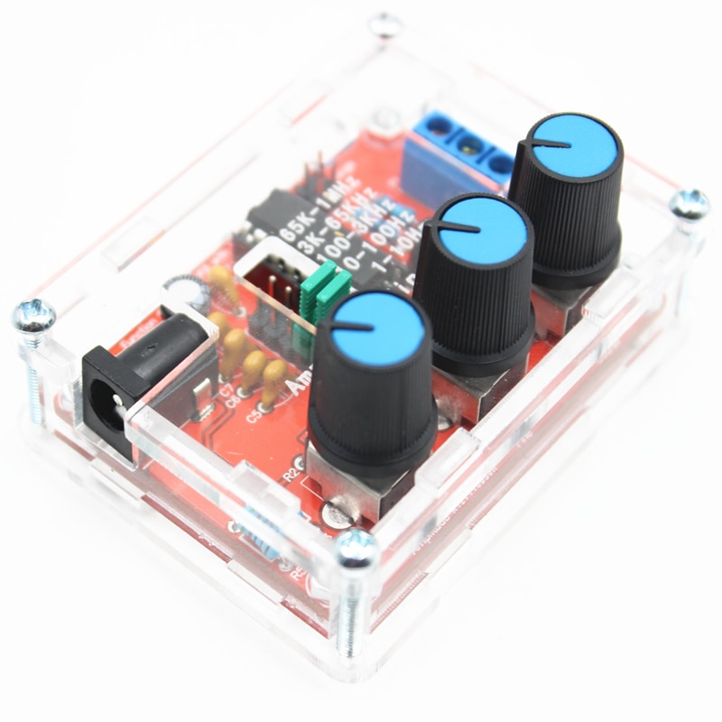


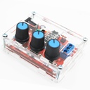

1Hz-1MHz Sine/Triangle/Square Output XR2206 Adjustable Frequency Signal Generator
Categories :
Signal GeneratorSKU :
1941156100% original guarantee
Return within 30days
Worldwide Fast delivery
You may also like

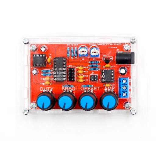

Parameters:
Voltage Supply: 9-12V DC Input
Waveforms: Square, Sine & Triangle
Impedance: 600 Ohm + 10%
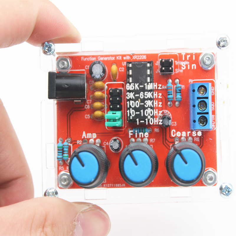
Frequency: 1Hz - 1MHz
SINE WAVE
Amplitude: 0 - 3V at 9V DC input
Distortion: Less than 1% (at 1kHz)
Flatness: +0.05dB 1Hz - 100kHz
SQUARE WAVE
Amplitude: 8V (no load) at 9V DC input
Rise Time: Less than 50ns (at 1kHz)
Fall Time: Less than 30ns (at 1kHz)
Symmetry: Less than 5% (at 1kHz)
TRIANGLE WAVE
Amplitude: 0 - 3V at 9V DC input
Linearity: Less than 1% (up to 100kHz) 10mA
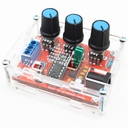
The welding installation considerations, follow these steps:
Welding IC socket, terminal blocks, finally power socket, adjustable potentiometer.
The back with a diagonal cutting pliers to cut short the pins as far as possible
The components are welding the front board, from low to high principles, namely the first low welding components, such as, capacitor, resistor, diode, etc.
Debugging steps:
After completion of welding on IC, XR2206, pay attention to the direction of IC, insert the might damage the chip!
check the IC whether against, such as anti please timely correction.
Insert the power supply, power supply for 5.5 * 2.1 port, inside outside is negative polarity. For 9-12 v power supply voltage. The waveform may not be stable for more than 12V
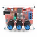
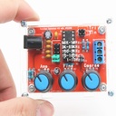
Using the step
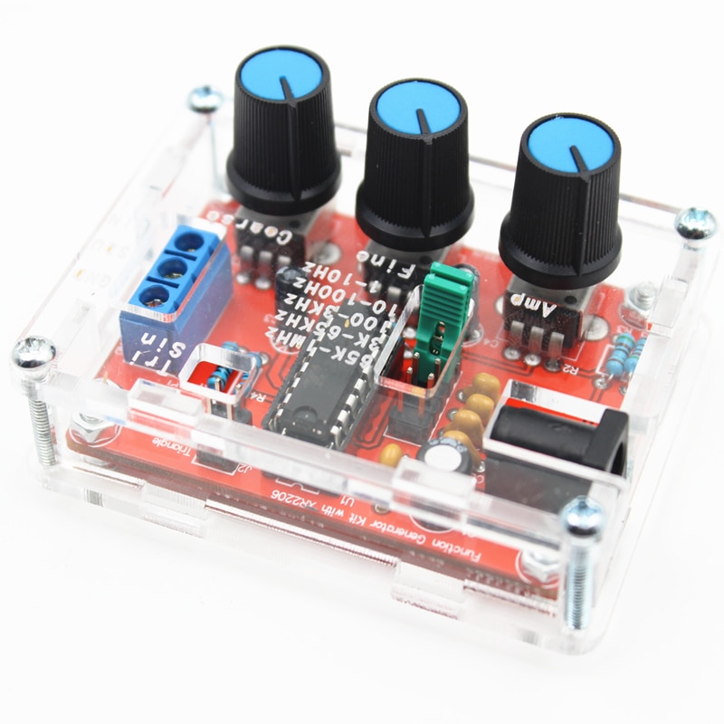
J1 jumper cap plug in, SIN/TRI blue terminals output sine wave (note J1, J2 can only insert one of)
J2 jumper cap plug in, SIN/TRI blue terminals output triangular wave (note J1, J2 can only insert one of)
SQU blue terminals output pulse
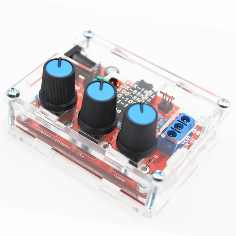
AMP : Sine wave, triangle wave amplitude adjustment
FINE : Frequency fine adjustment
Coarse : Frequency of coarse adjustment
Schematic diagram of Function Generator