


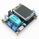


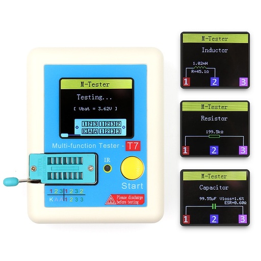
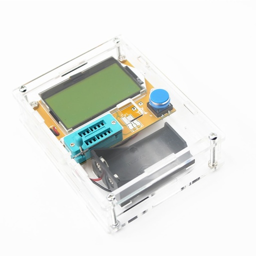
Mega328 LCR Diode Capacitance PWM Square Wave Frequency Signal Generator Transistor Tester
Categories :
Transistor TesterSKU :
1941178100% original guarantee
Return within 30days
Worldwide Fast delivery
You may also like
Features:
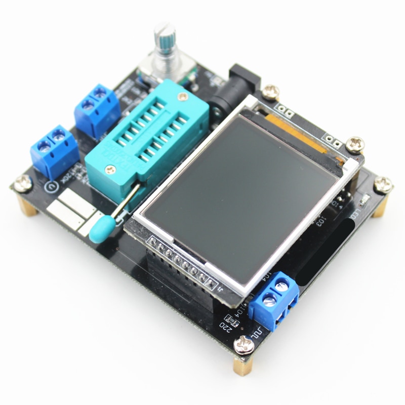
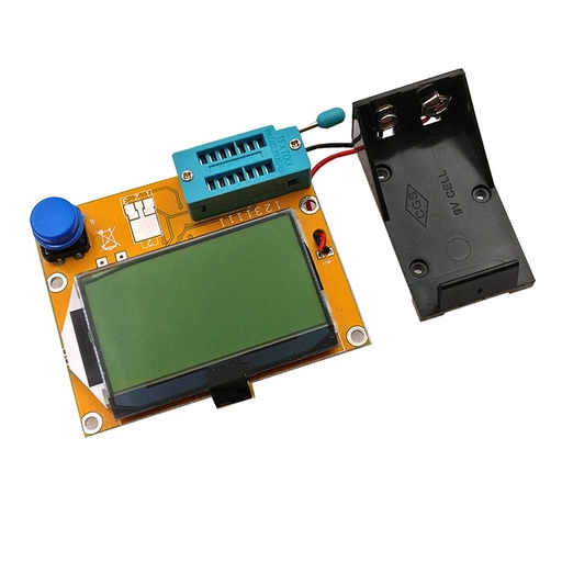
Transistor can be be powered with 6.8V – 12V DC. This can be achieve by a 9V layer-built battery. Two 3.7V lithium-ion battery in series or AC adapter. When powered on, the current is about 30mA at DC 9V.
Transistor Tester is controlled by a “rotary pulse encoder with switch” (RPEWS). There are 4 modes of operation - short press the knob, long press, left and right turning of the knob. Short press will switch on the transistor and start a test. It will turn off automatically at the end of the test. Long press and left or right turn will activate the function menu. Use > to select items. Press and hold the knob to exit the function menu.
The transistor has 3 test points, TP1, TP2, and TP3, within the test socket. To the right of the test socket is the SMT test pad with identifying numbers.
Attention: All ways be sure to discharge capacitors before connecting them to the tester to prevent damage. Extra caution is required if you try to test components mounted in a circuit. In either case the equipment should be disconnected from power source and you should be sure, that no residual voltage remains in the equipment.
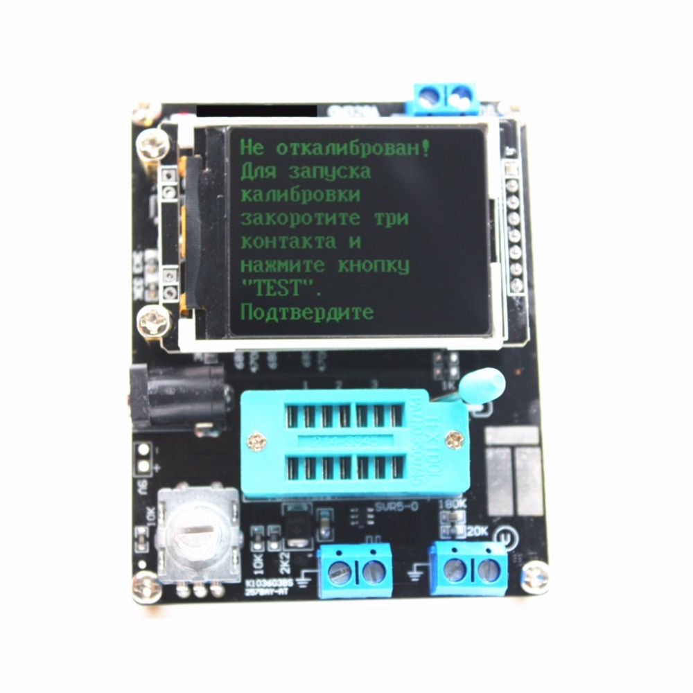
Self test and calibration:
The self test can be prepared by connecting all three test point together and pushing the RPEWS. To begin the self test, the RPEWS must be pressed again within 2 seconds. The tester with prompt you for the next step. Wait until the prompt says "isolate probes" and then disconnect the test points. Tester will soon display "1-||-3 > 100nf”. A capacitor with any capacity between 100nF and 20µF connected to pin 1 and pin 3 is required for the last task of calibration. You should connect the capacitor, after this text is shown. With this capacitor, the offset voltage of the analog comparator will be compensated for better measurement of capacity values.
Tips:
Normally the tester shows the battery voltage with every start. If the voltage fall below a limit, a warning is shown. If you use a rechargeable 9V battery, you should replace the battery as soon as possible or you should
recharge. If you try to measure little resistor values, you should keep the resistance of plug connectors and cables in mind. The quality and condition of plug connectors are important, also the resistance of cables used for measurement. The same is inforce for the ESR measurement of capacitors. With poor connection cable a ESR value of 0.02ohm can grow to 0.61ohm. You should not expect very good accuracy of measurement results, especially the ESR measurement and the results of inductance measurement are not very exact
Components with problems:
You should keep in mind by interpreting the measurement results, that the circuit of the transistor tester is designed for small signal semiconductors. In normal measurement condition the measurement current can only reach about 6 mA. The tester often cannot deliver enough ignition current or holding current for power thyristors or triacs. So a thyristor can be detected as NPN transistor or diode or detected as unknown.
Another problem is the identification of semiconductors with integrated resistors. So the base emitter diode of a BU508D transistor cannot be detected by reason of the parallel connected internal 42ohm resistor. Therefore the transistor function cannot be tested. Problem with detection is also given with power darlington transistors. We can find often internal base emitter resistors, which makes it difficult to identify the component with the undersized measurement current.
Measurement of PNP and NPN transistors:
For normal measurement the three pins of the transistor will be connect in any order to the measurement inputs of the transistor tester. After pushing the RPEWS, the Tester shows in row 1 the type (NPN or PNP), a possible integrated protecting diode of the Collector - Emitter path and the sequence of pins. The diode symbol is shown with correct polarity. Row 2 shows
the current amplification factor (hfe=...) and the Base - Emitter threshold voltage. The tester can measure the amplification factor with two different circuits, the common Emitter and the common Collector circuit (Emitter follower). Only the higher result is shown on the LCD. With Germanium transistors often a Collector cutoff current ICEO with current less base or a Collector residual current ICES with base hold to the emitter level is measured
Measurement of JFET and D-MOS transistors:
Because the structure of JFET type is symmetrical, the Source and Drain of this transistor cannot be differed. Normally one of the parameter of this transistor is the current of the transistor with the Gate at the same level as Source. This current is often higher than the current, which can be reached with the measurement circuit of the transistor tester with the 680ohm
resistor. For this reason the 680ohm resistor is connected to the Source. Thus the Gate get with the growing of current a negative bias voltage. The Tester reports the Source current of this circuit and additionally the bias voltage of the Gate. So various models can differ. The D-MOS transistors (depletion type) are measured with the same method.
You should know for enhancement MOS transistors (P-E-MOS or N-E-MOS), that the measurement of the gate threshold voltage (Vth) is more difficult with little gate capacity values. You can get a better voltage value, if you connect a capacitor with a value of some nF parallel to the gate/source. The gate threshold voltage will be find out with a drain current of about 3.5mA for a P-E-MOS and about 4mA for a N-E-MOS
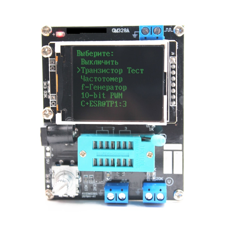
Function menu descriptions:
1. Switch off
Enter this Function the Tester will shut down immediately.
2. Transistor
Transistor test, it's also the default Function at switch on.
3. Frequency
Measurement of frequency, For frequencies below 25kHz the normal measurement is followed by a measurement of period time. This additional measurement is only followed after a normal frequency measurement.
4.f-Generator
Signal generation, this Function can output square wave .with various of frequency to choice.
5. 10-bit PWM
The function "10-bit PWM"(Pulse Width Modulation) generates a fixed frequency(7812.5Hz) with selectable pulse.